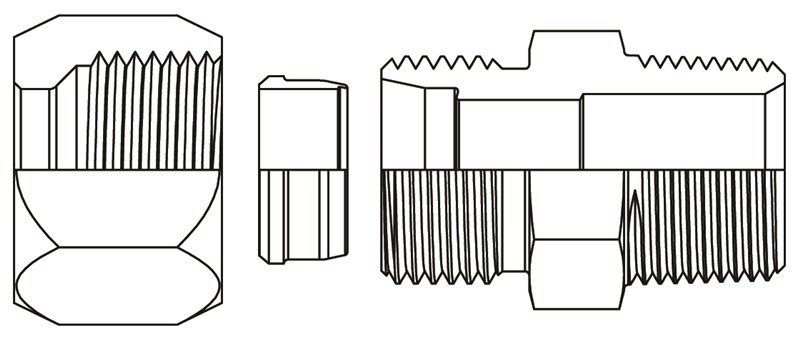
7000 Series Fittings consist of three main components: Bodies, Nuts, and Sleeves.
Bodies – Straight bodies are machined from bar stock. Shape fittings (elbows, tees, & crosses) are machined
from forgings. 7000 Series fittings are machined with NPTF - Dryseal Pipe Threads and SAE straight threads for easy installation.
Tube Nuts – Tube nuts in sizes 1/4", 5/16 ', 3/8", 1/2", 5/8", 3/4", 1" are Cold Formed in 1010 steel. Tube nuts in sizes 1 1/4", 1 1/2", & 2" are hot forged from 1045.
Tube Sleeves – Flareless tube sleeves are machined from cold drawn12L14 bar stock and are available in both SAE
"A" and "B" styles (see tube sleeve drawings to view the "A" and "B" style sleeves). After machining and inspection
the tube sleeves are heat treated to provide them with the necessary hardness.
CAUTION:
Stainless steel sleeves must be preset into tubing
during installation.
For use with applications such as: Construction machinery, Textile machinery, Machine tools, Chemical, Marine, Military, and most other high pressure hydraulic applications.Applications using thick wall tubing where flaring is not practical.
CAUTION:
7000 Flareless Fittings are NOT RECOMMENDED for use in instrumentation applications where toxic and
noxious gases are present.
Working Pressure up to 8000 PSI.
CAUTION:
Working pressures will vary depending on tube and fitting size. (For applications using extreme pressures at 5000 PSI or above (or) for application with extreme pressure fluctuations, contact World Wide Fittings.)
- Steel – Forged Bodies 1045
- Straight Bodies 12L14, 1045
- Cold Formed Nuts 1010
- Bar Stock Nut 12L14
- Flareless Sleeves 12L14
- Stainless Steel – Forged Bodies 316
- Stainless Steel – Straight Bodies 316
- Stainless Steel –Bar Stock Nuts 316
- Stainless Steel –Flareless Sleeves 17-4PH
Clear Zinc Trivalent
Alternate plating finishes are available upon request. Contact World Wide Fittings for details.
-30 Degrees Fahrenheit to +450 Degrees Fahrenheit Straight thread fittings which use "O" Rings to seal are restricted to the temperature range of the material used to construct the "O" Ring.
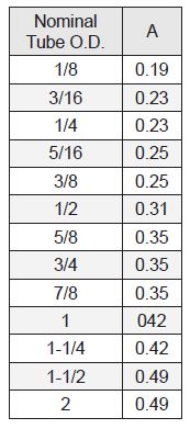
Tubing sizes are measured in sixteenths of an inch. Available sizes are 1/8" through 2". When ordering, the tube end of the fitting must be specified first followed by the pipe thread or straight thread end. All fittings in this section are ordered as assemblies only unless otherwise specified by customers when ordering. (Contact World Wide Fittings when ordering fittings as bodies only or configurations which are non-standard.)
7000 Series fittings meet SAE J514 and MS (Military Specifications).
Using a presetting tool, the flareless sleeve should be preset and inspected before final assembly of the fittings is made. All Stainless Sleeves must be preset before final installation.
- Cut the tubing to the desired length making sure the ends are square. (Refer to the tube penetration chart when measuring tube length.) Remove all burrs and foreign matter from the end of the tubing and clean thoroughly.
- Lubricate the threads of the preset body, tube nut, and outer edge of both ends of the flareless sleeve.
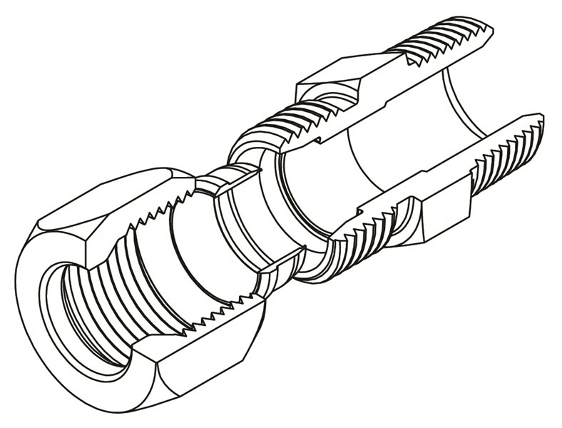
- Slide the tube nut and the flareless sleeve onto the tubing making sure the open end of the nut and the leading "bite" edge of the sleeve are facing the end of the tubing.
- Insert the tubing into the preset body until it hits the bottom or shoulder of the tool. Bring the flareless sleeve and tube nut down to the preset tool and tighten the nut to the finger-tight position.
- Using a marker make a reference line on the tubing and tube nut. Holding the tubing firmly in the preset tool and using a wrench, tighten the tube nut an additional 1-3/4 turns past the finger-tight position. Disassemble the nut from the preset tool and inspect the flareless sleeve for the proper bite into the tube. (Refer to example drawings for correct and incorrect preset sleeves.)
- Should the preset sleeve look acceptable, insert the tube with the preset sleeve into the fitting body to be assembled. Tighten the tube nut to the finger-tight position. Then using a wrench tighten the nut until a sudden rise in torque is felt. From the point where the sudden rise in torque started turn the nut an additional 1/3 to 1/4 turn. Your assembly is now ready for use. (Refer to the assembly torque charts during installation of 7000 series fittings from the port and thread assemblies section.)
____________________________________________________________
Incorrect tube / sleeve assembly
Shallow Bite
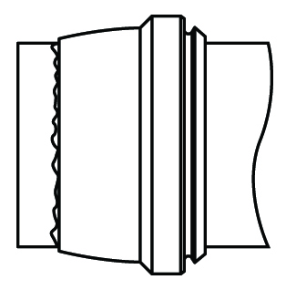
Tube Not Bottomed In Fitting
Sleeve Was Cocked
Over Set Sleeve
No Bite
____________________________________________________________
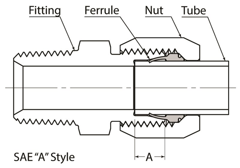
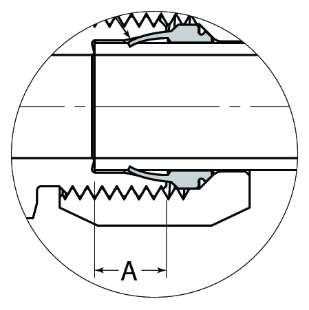
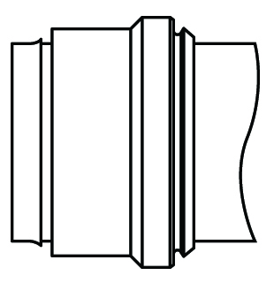
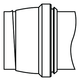
The above example shows an assembly using the SAE "A" Style flareless sleeve. When assembled properly the SAE "A"style flareless sleeve assembly will exhibit the following characteristics.
- 1. A slight indentation around the end of the tube which indicates that the tube was fully inserted during installation.
- A visible metal lip will have been raised 75% to 100% of the thickness of the sleeves lead biting edge all the way around the tube. (See illustration above.)
- The midsection of the sleeve behind the leading edge has a slight bow to provide contact with the internal taper of the fitting body and form a sealing point.
- The back (tail) end of the sleeve will be in firm contact with the O.D. of the tube.
___________________________________________________________________
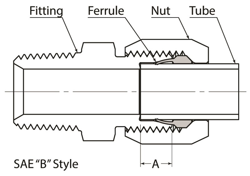
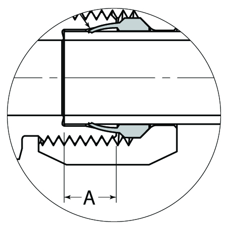
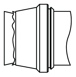
The above example shows an assembly using the SAE "B" Style flareless sleeve. When assembled properly
the SAE "B" style flareless sleeve assembly will exhibit the following characteristics.
- 1. A slight indentation around the end of the tube which indicates that the tube was fully inserted during installation.
- A metal lip will have been raised 75% to 100% of the thickness of the sleeves biting edge which is hidden under the leading end of the sleeve. (See illustration above.)
- The midsection of the sleeve behind the leading edge has a slight bow to provide contact with the internal taper of the fitting body and form a sealing point.
- The back (tail) end of the sleeve will be in firm contact with the O.D. of the tube.