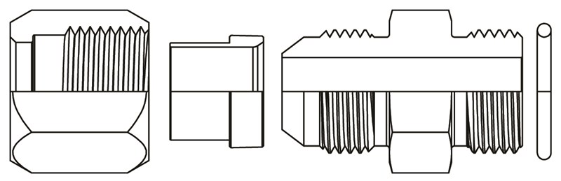
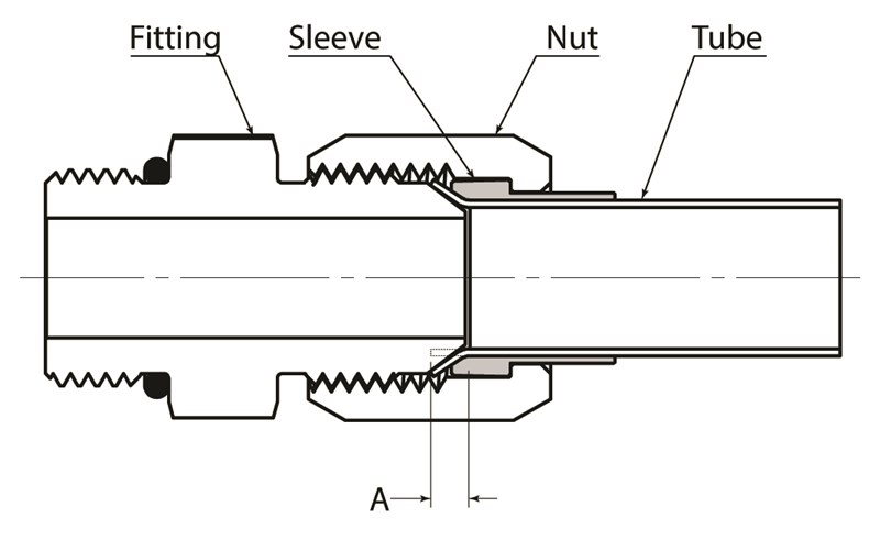
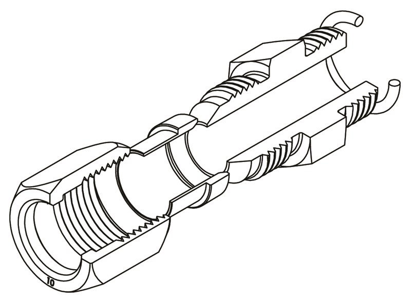
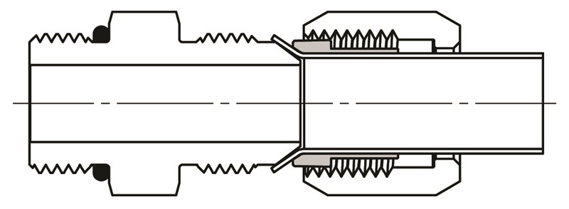
5000 Series Fittings consist of three main components: Bodies, Nuts, and Sleeves.
Bodies – Straight bodies are machined from bar stock. Shape fittings (elbows, tees, & crosses) are made from forgings.
Tube Nuts – Tube Nuts in sizes 1/4”, 3/8”, 1/2”, 5/8”,3/4”, 1”, are Cold Formed in 1010 steel. Tube Nuts in sizes 1/8”,
3/16”, 5/16”, 7/8”, 1-1/4”, 1-1/2”, & 2” are hot forged from 1045.
Tube Sleeves – Tube Sleeves for 5000 series fittings are
machined from 12L14 bar stock.
For use with machine tools, agricultural and earth moving machinery, instrumentation, chemical processing systems, and most other high pressure hydraulic applications.
Working pressures up to 5000 PSI. Working pressures will vary depending on tube and fitting size. (For applications using extreme pressures at 5000 PSI or above, contact World Wide Fittings.)
Steel – Bar Stock 12L14, 1045 Cold Formed 1010
Stainless Steel – Type 316
Clear Zinc Trivalent
Passivated
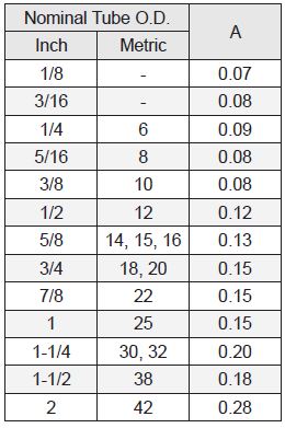
Tubing sizes are measured in sixteenths of an inch. Available sizes are 1/8” through 2”. When ordering, the
tube end of the fitting must be specified first followed by the pipe thread or straight thread end. All fittings in this section are ordered as bodies only unless specified by customers when ordering. (Contact World Wide for details on ordering fittings preassembled with nuts and sleeves.)
5000 Series Fittings Meet SAE J514 and MS
(Military Specifications).
- Cut the tubing to the desired length making sure the ends are square. Remove all burrs from the tubing ends and clean thoroughly.
- Slide the tube nut on the tubing making sure that the open end of the nut is facing the tube end. Then slide the tube sleeve on the tubing making sure the seat of the sleeve is facing the tube end.
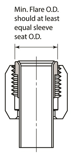
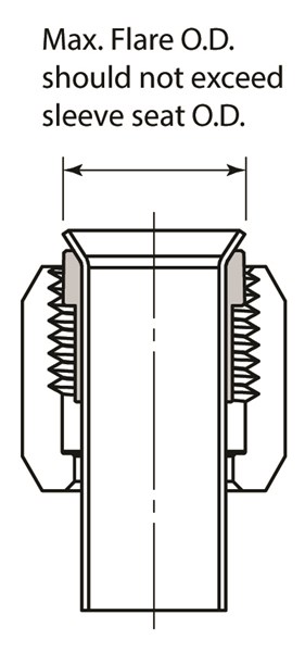
- Using a 37° flaring tool, flare the tubing end. Inspect the flared end for dimensions that are out of tolerance and may cause underflare, overflare, and excessive wall thinning which can interfere with the operation and quality of the assembled fitting. (For examples of underflaring and overflaring refer to the tube flaring drawings.)
- Pull the sleeve up to the flared end and then pull the tube nut up and over the sleeve and flared end.
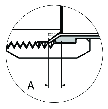
- Lubricate the threads on both the nut and the fitting body, align the flared end against the nose of the fitting and assemble to the finger-tight position.
- Using a wrench tighten the assembly until the nut is snug, then tighten the nut an additional one to two flats further. (Refer to the assembly torque charts during installation of 5000 series fittings from the port and thread assemblies section.)
Correct assembly
Incorrect assembly
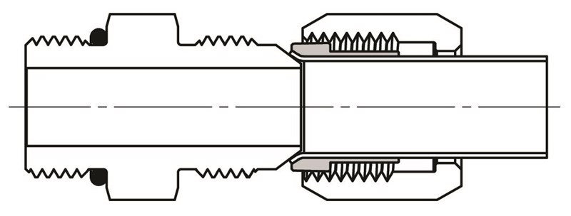
Underflaring reduces contact area causing excessive nose collapse and leakage; or in extreme cases, tube pull out under pressure.
Overflaring causes tube nut thread interference, either preventing assembly altogether, or giving a false sense of joint tightness resulting in leakage.